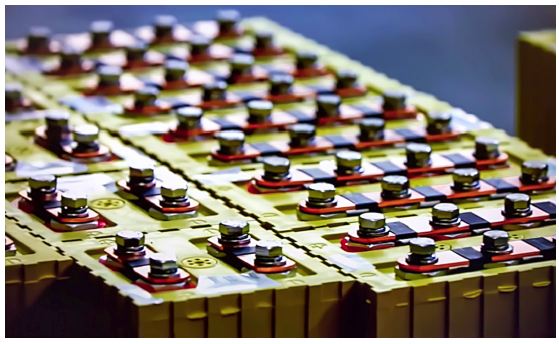
Designing a smart sensor for an electric vehicle’s battery requires some intelligent planning to overcome the associated mechanical and electrical challenges. For example, a car manufacturer may use different battery configurations for different models. Modifying the battery mechanical design to match each configuration is expensive and can trigger development and production delays. The voltage and current measurements must be accurate while performed in a noisy environment. The busbars connecting the battery modules and sub-modules (Figure 1) may be tight with screws that, when loose, can produce highly resistive losses or interrupt the entire current flow.
In this design solution, we review these challenges and propose an innovative solution that allows for a flexible battery configuration that saves cost and speeds time to market. With this solution, the voltage across each cell is measured with high accuracy for reporting and balancing; the voltage across busbars is also easily measured and reported for fault detection.

Typical Battery Configuration
As an example, a 42A, 402.3V electric car battery may be composed of a series of 8 modules, each with a developing voltage of 50.3V.
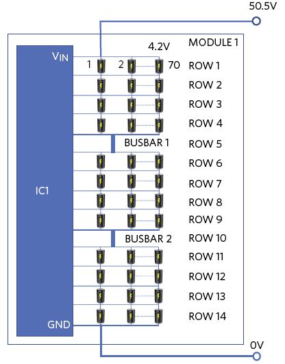
In Figure 2, a single module is composed of three 4-series, 70-parallel submodules (4S) connected by busbars (BB). Accordingly, the module’s configuration is: 4S+BB+4S+BB+4S.

Lack of Flexibility
In a traditional module, moving from a 14s to a 12s module is problematic. The removal of the top two rows in Figure 2 leaves the input of the IC (VIN) unconnected. This requires a PCB change to connect VIN to the top of row 3.
Noise
Automobiles have harsh and noisy electrical environments. Additionally, during charge, noise from the power mains (110VAC, 60Hz or 220VAC, 50Hz) affects the voltage measurement of the car battery pack with an aliasing error. Multiple levels of filtering then become necessary.
Poor Busbar Contacts
A 1/8in x 2in copper bar that is 1 foot long can carry 500A and has a resistance of 33μΩ. Accordingly, a 42A current will cause a voltage drop of 33μΩ x 42 = 1.4mV in normal operation. During fast charge, say with 300A, the voltage drop is only 33μΩ x 300 = 9.9mV. Clearly the busbar is not a problem under normal circumstances. However, if the busbar contacts deteriorate for any reason, the resistance can dramatically increase, compromising the battery operation.
The Solution
As an example, the MAX17853 is a flexible data-acquisition system for the management of high-voltage and low-voltage battery modules. The system can measure 14 cell voltages and a combination of six temperatures or system voltage measurements with fully redundant measurement engines in 263μs. It can also perform all inputs solely with the ADC measurement engine in 156μs. There are 14 internal balancing switches rated for > 300mA for the cell-balancing current, each supporting extensive built-in diagnostics. Up to 32 devices can be daisy-chained to manage 448 cells and monitor 192 temperatures.
Flexpack
The IC implements the re-routing of the input voltage from the top row down to any cell below via software. This enables one BMS board for multiple battery module configurations and helps avoid a hardware redesign going from one model to another. This reduces costs for engineering development, inventory, and OEM re-qualification, as well as improves time to market.
Digital Filtering
In competing ΣΔ architectures, measurements are sequential, creating an overhead in the software processing the data. The IC’s SAR ADC system architecture has the advantage of 14 rows of measurements that are practically simultaneous. The measurement accuracy can be further improved with the addition of a digital lowpass noise filter.
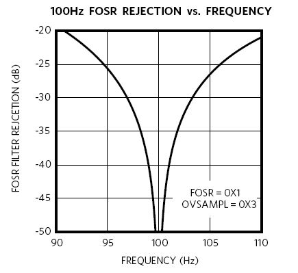
The IC has two levels of digital filtering. A special notch filter eliminates inaccuracies during charging due to the rectification of the charging line frequency (100Hz/120Hz) and simplifies overall system design. This improves time align sampling with the system charging circuit (Figure 3). A notch pass filter attenuates the generic noise associated with the harsh automotive environment.

Busbar Monitoring
The IC can easily monitor the busbar status in addition to measuring the cell voltages. Any cell can be used for cell voltage measurement or busbar monitoring. Cell and busbar voltages that range from -2.5V to +5V are measured differentially over a 65V common-mode range, with a typical accuracy of 1mV (3.6V cell, 25°C). Busbar measurements are completed with the same timestamp as cell and temperature measurements, allowing for true time-aligned measurements and monitoring.
Communications
For robust communications, the system uses a Maxim battery management UART or SPI protocol, and is optimized to support a reduced feature set of internal diagnostics and rapid-alert communication through both embedded communication and hardware-alert interfaces to support ASIL D and FMEA requirements.
Conclusion
In this design solution, we reviewed the limitations of existing battery management solutions, including lack of flexibility, difficulty in monitoring faulty busbars, and cell measurement accuracy in the presence of multiple noise sources. We then introduced a new IC that allows for a flexible battery configuration that saves cost and accelerates time to qualification and time to market. With this solution, the voltage across each cell is measured with high accuracy for reporting and balancing while the busbars are monitored for fault detection.
